10+ uml diagram c++
The CS System Data Flow Diagram example contains four processes two external entities and four data stores. UML 2x added the ability to decompose software system into components and sub.
How To Draw A Flowchart To Print Between 1 To 20 Even Numbers Quora
To show the relationship between classes B and A where B only uses static methods in A you use a dependency not an association.
. The United States government standardized Ada a systems programming language derived from Pascal and intended for use by defense contractors. Edraw UML Diagram is a new UML design tool which works in the. The four diagrams that were added are.
UML Diagram Maker is ideal for software engineers and software designers who need to draw detailed software design documentation. Keep your favorite diagram views and UML tools at your fingertips to improve efficiency and productivity. UML 2x has increased the number of diagrams from 9 to 13.
We use a black filled circle to depict the initial state of a system. Read through the diagram and then we will introduce some of the key concepts based on this diagram. Next lets create an external entity.
To show static methods and attributes you underline them in a UML class diagram. All timestamps displayed on the forums can be automatically corrected to show the correct time for your location in the world. Analysis and design of the static view of an application.
Supports following UML diagrams. The purpose of the class diagram can be summarized as. Nested Switch in C.
The class diagram can be used to show the classes relationships interface association and collaboration. In the New Diagram window select Data Flow Diagram and click Next. Everything is customizable in the UML diagrams you create with UModel size position color typeface characteristics and line styles.
The following is a thread-safe implementation. Enter your 10-Digit Active Mobile Number. An ER Model provides a means of communication.
C combined object-oriented and systems programming. The 1980s were years of relative consolidation. In C we can have an inner switch embedded in an outer switchAlso the case constants of the inner and outer switch may have common values and without any conflicts.
Figure notation for initial state or start state A process can have only one initial state unless we are depicting nested activities. It imports C and can export up to a wider range of languages. From the Diagram Toolbar drag Process onto the diagram.
Graphical editing tool for UML 2. Ward Cunningham Straight from the programming trenches The Pragmatic Programmer cuts through the increasing specialization and technicalities of modern software development to examine the core process--taking a requirement and producing working maintainable code that delights its users. Define your own graphical textual or tabular notation.
2001-04-10 Similar Business Software Altova UModel. Break down of the CS System process shown in the context DFD. It provides high Performance.
Obeo Windows macOS Linux 2012 2019-01-30 v900 Yes EPL Java Sirius. C Java SQL C Perl Python Tcl and PHP. For objects this is the state when they are.
Interaction overview diagram. Windows 7 8 10 versions supported. Software Ideas Modeler can generate code from UML diagramsThere are pre-defined templates that allow you to turn your UML Class Diagram with all the classes interfaces enumerations and various relationships to source code in Java C Python C or other languages.
Well now draw the first process. Timing diagram communication diagram interaction overview diagram and composite structure diagram. Activity Diagram Notations Initial State The starting state before an activity takes place is depicted using the initial state.
UML to Code. Use case diagram Sequence diagram Collaboration diagram Class diagram Statechart diagram Activity diagram Component diagram Deployment diagram and Package. Unified Modelling Language UML is a modeling language in the field of software engineering which aims to set standard ways to visualize the design of a system.
This open source database tool provides Scalability and Flexibility. C KDE UML Designer. To create new DFD select Diagram New from the toolbar.
It allows you to create all of the UML diagrams. It provides editors for all the UML diagrams Class Diagram Object Diagram Package Diagram Composite Structure Diagram Component Diagram Deployment Diagram Profile Diagram Use case Diagram and more. UML state machine also known as UML statechart is an extension of the mathematical concept of a finite automaton in computer science applications as expressed in the Unified Modeling Language UML notation.
一概念组件图Component Diagram又称为构件图他描述的是在软件系统中遵从并实现一组接口的物理的可替换的软件模块构件图 构件Component 接口Interface 关系Relationship 端口Port 连接器Connector在面向对象系统的物理方面进行建模要用到两种图组件图和配置图. UML 2x renamed statechart diagrams to state machine diagrams. Static features are underlined.
The UML designer tool helps in modifying and envisioning UML25 models. A sequence diagram is the most commonly used interaction diagram. Class diagrams are the main building blocks of every object-oriented method.
ER Diagram is known as Entity-Relationship Diagram it is used to analyze the structure of the Database. The Library Management System database keeps track of readers with the following considerations. You can specify logical types for the attributes and operation.
The figure below shows the level 1 DFD which is the decomposition ie. It is the most popular UML diagram in the coder community. Name the new process System.
This UML diagram maker provides the best functionality expected from a UML tool like a large selection of supported diagrams. This free database software for Windows 10 has Robust Transactional Support. Enter Context as diagram name and click OK to confirm.
In Japan and elsewhere vast sums were spent investigating the so-called fifth-generation languages that. See UML Distilled p66 or section 7319 Feature of the UML Superstructure specification. UML guides the creation of multiple types of diagrams such as interaction structure and behaviour diagrams.
The concepts behind it are about organizing the way a device computer program or other often technical process works such that an entity or each of its. It shows relationships between entities and their attributes. It provides transparency to work on DSL as well as UML models.
UML diagrams like activity diagram sequence diagram can only give the sequence flow of the application however class diagram is a bit different. We considere the following program which the user to type his own ID if the ID is valid it will ask him to enter his password if the password is correct the program will print. It is one of the best UML diagram tool which supports code generation as well as reverse engineering for C and Java.
This free SQL database tool has web and data warehouse strengths. The UMLet Team Windows macOS Linux. The class diagram clearly shows the mapping with object-oriented languages such as Java.
A singleton implementation may use lazy initialization where the instance is created when the static method is first invokedIf the static method might be called from multiple threads simultaneously measures may need to be taken to prevent race conditions that could result in the creation of multiple instances.

Software Development Wikiwand
Flowchart Symbols

Diagrams Easy Redmine 10 Youtube
1
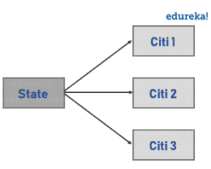
What Is Association In Java Oops Concepts With Examples Edureka
3

Are There Any Tools That Would Allow Me To Easily Create An Interactive Software Architectural Diagram Quora

Cs 383 Software Engineering
2
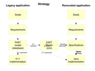
Renovating A 15 Year Old Model Driven Application

Pin On Report Template
1
What Is An Algorithm For Printing A Table Of 2 Quora
How Do We Read Cardinality In A Uml Diagram Or In E A Diagram Quora
What Are The Best Uml Tools For Linux Quora
How To Draw A Flowchart To Print Between 1 To 20 Even Numbers Quora
What Is Meant By Uml Diagram Quora